I.1 Lateral Analysis横向分析
I.1.1 General概述
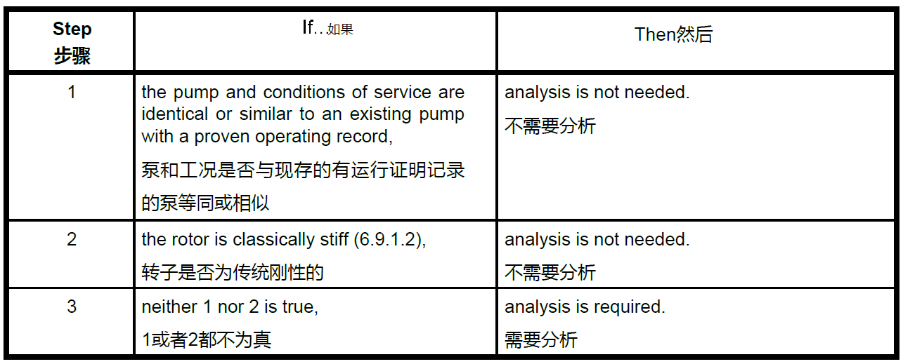
If a lateral analysis is required (see 9.2.4.1), the method and assessment of results shall be as specified in
I.1.2 through I.1.5. Table I.1 illustrates the analysis process. The method and assessment specified are peculiar to horizontal-axis liquid-handling turbomachines.
如果需要进行横向分析(见 9.2.4.1),其方法和结果评估应符合 I.1.2 至 I.1.5 的规定。表 I.1 说明了分析过程。本节规定的方法和评估,是水平轴向液体处理涡轮机械所特有的。
==Table I.1 Rotor Lateral Analysis Logic Diagram
表I.1—转子横向分析逻辑表==
I.1.2 Natural Frequencies固有频率
The report shall state the following:
报告应该说明如下内容:
- a) the rotor's first, second, and third “dry” bending natural frequencies (see 6.9.1.2);
转子的第一、第二和第三 "干 "弯曲固有频率(见 6.9.1.2);
NOTE 1 The “dry” bending natural frequencies serve as useful reference points for subsequent analysis of the
damped natural frequencies.
注1:"干 "弯曲固有频率可作为后续分析阻尼固有频率的有用参考。
NOTE 2 Usual design practice is to investigate overhung modes, coupling, and thrust collar and set their first bending natural frequency at separation margin at least 20 % above the highest potential excitation frequency (based on maximum continuous speed) before carrying out lateral analysis of the rotor.
注 2: 通常的设计做法是,在对转子进行横向分析之前,先研究悬臂模态、联轴器和推力盘,并将他们第一弯曲固有频率设定为比最大潜在激励频率(基于最大持续转速)至少高 20% 的隔离裕度。
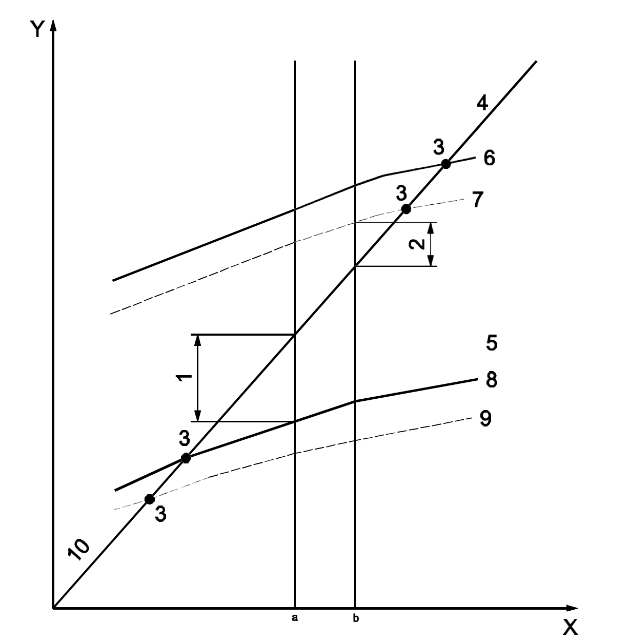
- b) all the rotor's damped natural frequencies within the frequency range zero to 2.2 times maximum continuous speed, which shall be calculated for the speed range 25 % to 125 % of rated, taking account of the following:
在0 至 2.2 倍最大连续转速的频率范围内所有转子的阻尼固有频率,应在额定转速的 25 % 至 125 % 的范围内计算,并考虑以下因素
- stiffness and damping at the following internal running clearances at the expected temperature:
在预期温度下,下列内部运行间隙处的刚度和阻尼:
as-new clearances, with water,
用水形成的新间隙
as-new clearances, with the pumped liquid,
用泵送液体形成的新间隙
2 (two times) the as-new clearances, with the pumped liquid;
用泵送液体形成的2倍新间隙
stiffness and damping at the shaft seals (if labyrinth type);
轴封处的刚度和阻尼(如果使用拉别令轴封)
stiffness and damping within the bearings for the average clearance and oil temperature. The effect of bearing stiffness and damping in pumps is generally minor in comparison to that of the internal running clearances; therefore, it is sufficient to analyze the bearings at their average clearance and oil temperature;
在平均间隙和油温下,轴承内部的刚度和阻尼。与内部运行间隙相比,泵中轴承刚度和阻尼的影响通常较小;因此,只需分析平均间隙和油温下的轴承即可;
mass and stiffness of the bearing support structure;
轴承支撑结构的质量和刚度;
inertia of the pump half-coupling hub and half the coupling spacer;
泵半联轴器轮毂和半联轴器加长段的惯性;
NOTE Though the higher order damped natural frequencies can be close to impeller vane passing frequency, there is no experience in liquid-handling turbomachines pointing to rotor-dynamics problems caused by such proximity. This is deemed a consequence of the complex mode shape(s), relatively low excitation energy, and sufficient damping at the higher frequencies involved.
注:虽然高阶阻尼固有频率可能接近叶轮叶片的通过频率,但在液体处理涡轮机械中没有任何经验表明这种接近会导致转子动力学问题。这被认为是由于复杂的模态形状、相对较低的激励能量以及较高频率下充足的阻尼而导致的。
::: tip
解释:vane passing frequency(叶片通过频率),之前解释过。
:::
- c) values or the basis of the stiffness and damping coefficients used in the calculation.
值或刚度和阻尼系数的基础(计算中使用的)。
I.1.3 Separation Margins and Damping隔离裕度和阻尼
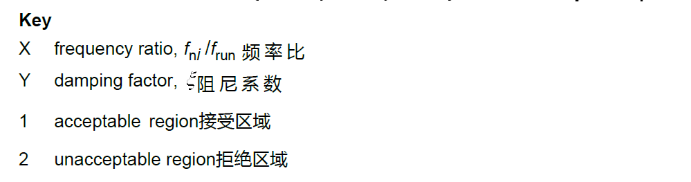
For both as-new and 2x as-new clearances, the damping factor vs separation margin between any bending
natural frequency and the synchronous run line shall be within the “acceptable” region shown on Figure I.1. If
this condition cannot be satisfied, the damped response to unbalance shall be determined (see I.1.4).
对于全新间隙和 2 倍全新间隙,任何弯曲固有频率与同步运行线之间的阻尼系数与隔离裕度必须在图 I.1 所示的 "可接受 "区域内。如果无法满足这一条件,则应确定对不平衡的阻尼响应(见 I.1.4)。
NOTE In liquid-handling turbomachines, the first assessment of a rotor's dynamic characteristics is based on damping vs separation margin, rather than amplification factor vs separation margin. Two factors account for this basis. First, the rotor's natural frequencies increase with rotational speed, a consequence of the differential pressure across internal clearances also increasing with rotational speed. On a Campbell diagram (see Figure I.2), this means that the closer separations are between the running speed and natural frequencies rather than between the running speed and the critical speeds. Because the amplification factor at the closer separations is not related to synchronous (unbalance) excitation of the rotor, it can be developed only by an approximate calculation based on the damping. Second, employing damping allows the specification of a minimum value for natural frequency to running speed ratios from 0.8 to 0.4, thereby assuring that the rotor is free from significant subsynchronous vibration.
注:在液体处理涡轮机械中,转子动态特性的首次评估基于阻尼与隔离裕度,而不是放大系数与隔离(间隔)裕度。有两个因素决定了这一基础。首先,转子的固有频率随转速的增加而增加,这是内部间隙压力差也随转速增加而增加的结果。在坎贝尔图上(见图 I.2),这意味着较近的间隔是运行速度和固有频率之间的间隔,而不是运行速度和临界速度之间的间隔。由于较近间隔处的放大系数与转子的同步(不平衡)激励无关,因此只能根据阻尼进行近似计算。其次,采用阻尼可以将固有频率与运行速度比的最小值规定为 0.8 至 0.4,从而确保转子不会产生明显的次同步振动。
I.1.4 Damped Unbalance Response Analysis阻尼不平衡响应分析
If the damping factor vs separation margin for a mode or modes is not acceptable by the criteria in Figure I.1, the rotor's damped response to unbalance shall be determined for the mode(s) in question on the following basis:
如果按照图 I.1 中的标准,某一模式或多个模式的阻尼系数与隔离裕度不合格,则应根据以下基础确定转子对不平衡的阻尼响应:
a) the pumped liquid;
泵送液体
b) clearance condition(s), as-new or 2 x as-new, causing inadequate separation margin vs damping;
间隙情况,(全新或 2 x 全新),导致隔离裕度与阻尼的不足;
c) total unbalance of four times (4x ) the allowable value (see 9.2.4.2.1) lumped at one or more points to excite the mode(s) being investigated.
在一个或多个点上叠加四倍的允许值(见 9.2.4.2.1)的总不平衡,以激发所研究的模式。
Only one mode shall be investigated in each computer run.
在每次计算机运行中只能核查一种模态。
I.1.5 Allowable Displacement允许的位移
The peak-to-peak displacement of the unbalanced rotor at the point(s) of maximum displacement shall not exceed 35 % of the diametral running clearance at that point.
不平衡转子在最大位移点的峰峰位移不得超过该点直径方向运行间隙的 35%。
::: tip
解释:防止动静部件接触。
:::
NOTE In centrifugal pumps, the typical damped response to unbalance does not show a peak in displacement at resonance large enough to assess the amplification factor. With this limitation, assessment of the damped response to unbalance is restricted to comparing rotor displacement to the available clearance.
注:在离心泵中,典型的不平衡阻尼响应在共振时,不会出现足以评估放大系数的位移峰值。受此限制,对不平衡阻尼响应的评估仅限于比较转子位移和可用间隙。
I.2 Shop Verification of Rotor Dynamic Characteristics车间转子动力学特性验证
I.2.1 If specified, the dynamic characteristics of the rotor shall be verified during the shop test. The rotor's actual response to unbalance shall be the basis for confirming the validity of the damped lateral analysis. This response is measured during either variable-speed operation from rated speed down to 75 % of the first critical speed or during coast-down. If the damped response to unbalance was not determined in the original rotor analysis (see I.1.4), this response shall be determined for a pump with new clearances handling water before proceeding with shop verification. The test unbalances shall be vectorially added in phase with the residual unbalance, at locations determined by the manufacturer (usually at the coupling and/or thrust collar).
如有规定,转子的动力学特性须在车间试验中验证。转子对不平衡的实际响应应作为确认阻尼横向分析有效性的依据。该响应是通过变速操作或者停机过程中,从额定转速降至一阶临界转速的 75% 的过程中测量的。如果在最初的转子分析(见 I.1.4)中未确定进行不平衡的阻尼响应,则在进行车间验证之前,应确定具有新间隙输送水的泵的响应。测试不平衡应在制造商确定的位置(通常在联轴器和/或止推环处)与残余不平衡相位矢量叠加。
NOTE The principal objective of shop verification by response to unbalance is to verify the existence of a critical speed (vibration peak) within the tolerance of the calculated value or, if the analysis predicted a highly damped critical speed, the absence of a vibration peak within tolerance of the calculated value. Shop verification by this method is feasible only for pumps that have sleeve bearings and that are furnished with proximity probe pairs at each journal bearing.
注:通过不平衡响应进行车间验证的主要目的是验证是否存在计算值允差范围内的临界转速 (振动峰值),或者,如果分析预测临界转速阻尼较大时,则验证是否存在计算值允差范围内的振动峰值。通过这种方法进行车间验证仅适用于具有滑动轴承且每个轴颈轴承都配有成对接近探头的泵。
I.2.2 The magnitude and location of the test unbalance(s) shall be determined from a calibration of the rotor's sensitivity to unbalance. The calibration shall be performed by obtaining the vibration orbits at each bearing, filtered to rotor speed (1x ), during two trial runs as follows:
试验不平衡量的大小和位置应通过校准转子对不平衡的敏感度来确定。校准应在两次试运行期间,通过对转子速度 (1x ) 的滤波,获得每个轴承的振动轨道,具体方法如下:
a) with the rotor as-built;
使用最终的转子
b) with trial unbalance weights added 90° from the maximum displacement in Run a).
在a)项运行的最大位移上,增加 90°的试验不平衡砝码。
The magnitude of the test unbalances shall be such that the calculated maximum shaft displacement caused by the resultant total unbalance (residual plus test) is 150 % to 200 % of the allowable displacement from Table 8 or Table 9 at the bearing probes but shall not exceed eight times the maximum allowable rotor unbalance.
试验不平衡量的大小应使计算得出的总不平衡量(残余加上试验)引起的最大轴位移为轴承探头处允许位移的 150% 至 200%(表 8 或表 9 所列),但不得超过转子最大允许不平衡量的8倍。
I.2.3 During the test, the rotor's speed, vibration displacement, and corresponding phase angle, filtered to rotor speed (1x ), shall be measured and recorded.
试验期间,必须测量和记录转子的转速、振动位移和相应的相位角,并滤波至转子转速(1x )。
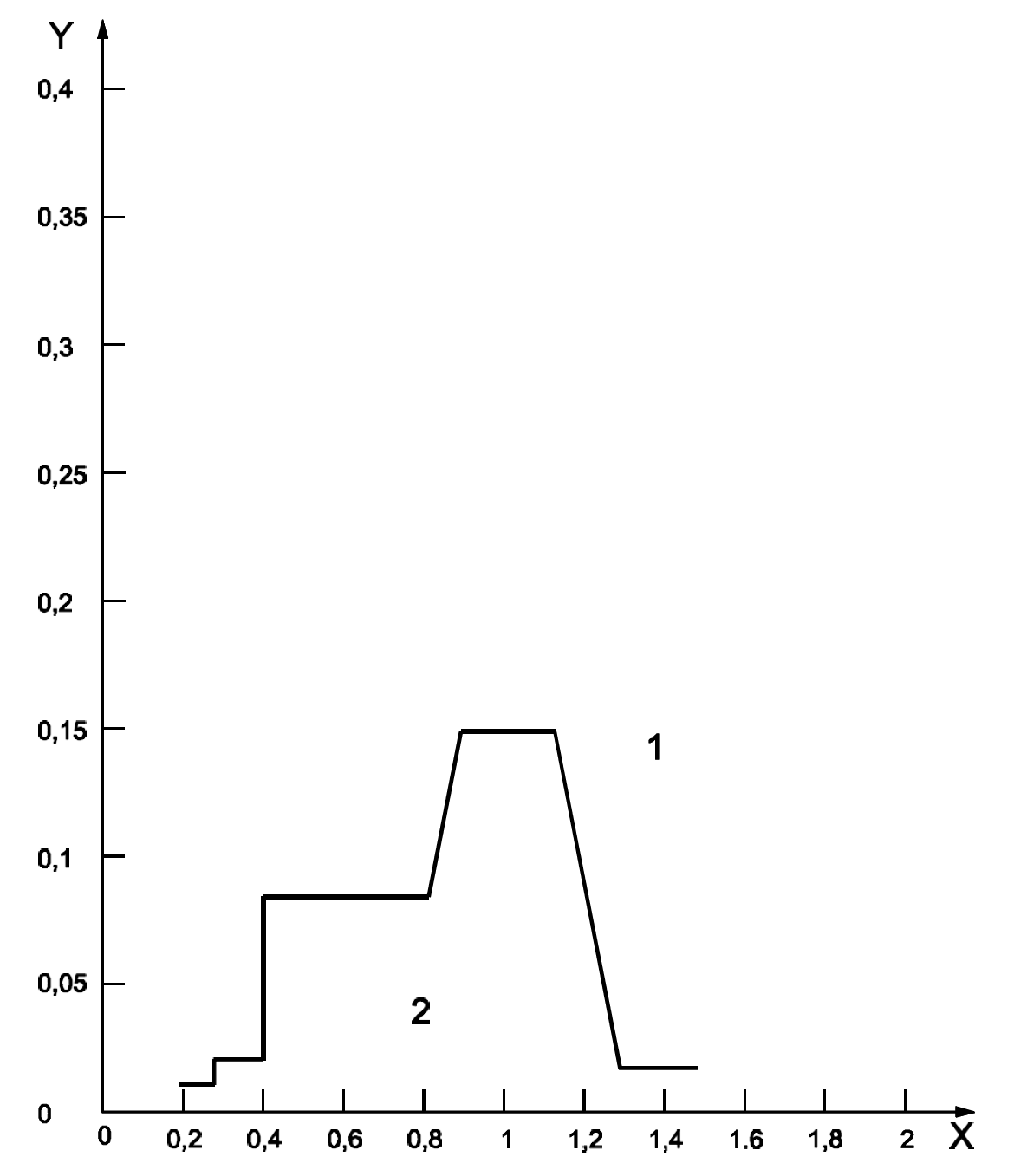
==Figure I.1 Damping Factor vs Frequency Ratio
图I.1—阻尼系数VS频率比==
==Figure I.2 Typical Campbell Diagram
图I.2—典型的坎贝尔图==
I.2.4 The rotor's characteristics shall be considered verified if the following requirements are met:
如符合下列要求,转子的特性应视为已验证:
a) observed critical speed(s) (distinct vibration peak and appropriate phase shift) within ±10 % of the calculated value(s);
观察到的临界转速(明显的振动峰值和适当的相移)在计算值的±10%范围内;
b) measured vibration amplitudes within 35 % of the calculated values.
测得的振幅不超过计算值的 35%。
Highly damped critical speeds might not be observable; therefore, the absence of rotor response in the region of a calculated highly damped critical speed is verification of the analysis.
高阻尼临界转速可能无法观测到;因此,在计算出的高阻尼临界转速区域内没有转子响应就是对分析的验证。
I.2.5 If the acceptance criteria given in I.2.4 are not met, the stiffness or damping coefficients, or both, used in the natural frequency calculation shall be adjusted to produce agreement between the calculated and measured results. The coefficients of one type of element, annular clearances with L/D<0.15, annular clearances L/D>0.15, impeller interaction, and bearings shall be adjusted with the same correction factor. Once agreement is reached, the same correction factors shall be applied to the calculation of the rotor's natural frequencies and damping for the pumped liquid, and the rotor's separation margins vs damping factors rechecked for acceptability.
如果不符合I.2.4中给出的验收标准,应调整固有频率计算中使用的刚度系数或阻尼系数,或两者都调整,以使计算结果和测量结果一致。某种类型元件的系数、L/D<0.15 的环形间隙系数、L/D>0.15 的环形间隙系数、叶轮相互作用和轴承应使用相同的修正系数进行调整。 一旦达成一致意见,应使用相同的修正系数计算转子的固有频率和泵送液体的阻尼,并重新验证转子的隔离裕度与阻尼系数的可接受性。
Of the coefficients used in rotor lateral analysis, those for damping in annular clearances have the highest uncertainty and are, therefore, usually the first that are adjusted. The stiffness coefficients of annular clearances typically have a low uncertainty and, therefore, shall be adjusted only on the basis of supporting data. Adjustments of bearing coefficients require specific justification because the typical values are based on reliable empirical data.
在转子横向分析中使用的系数中,环形间隙阻尼系数的不确定性最高,因此通常首先进行调整。环形间隙的刚度系数通常具有较低的不确定性,因此只能根据支持数据进行调整。轴承系数的调整需要具体的理由,因为典型值是基于可靠的经验数据。
I.2.6 Alternative methods of verifying the rotor's dynamic characteristics, e.g. variable-frequency excitation with the pump at running speed to determine the rotor s natural frequencies, are available. The use of alternative methods and the interpretation of the results shall be agreed between the purchaser and manufacturer.
可采用其他动态特性方法,例如在泵处于运行速度时进行变频激振,以确定转子的固有频率。替代方法的使用和对结果的解释应由买方和制造商商定。
I.3 Documentation文档
The report on a lateral analysis shall include the following:
横向分析报告应包括以下内容:
a) results of initial assessment (see 9.2.4.1);
初始评估结果(见 9.2.4.1);
b) fundamental rotor data used for the analysis, which may be the fundamental model;
用于分析的转子基本数据,可以是基本模型;
c) Campbell diagram (see Figure I.2);
坎贝尔图(见图 I.2)
d) plot of damping ratio vs separation margin;
阻尼比与分离裕度的关系图;
e) mode shape at the critical speed(s) for which the damped response to unbalance is determined (see I.1.4);
确定不平衡阻尼响应的临界转速下的模态振型(见 I.1.4);
f) Bode plot(s) from shop verification by unbalance (see I.2.3);
通过不平衡进行车间验证的 Bode 图(见 I.2.3);
g) summary of analysis corrections to reach agreement with shop verification (see I.2.5).
达到与车间验证一致的分析修正总结(见 I.2.5)。
Items e) through g) shall be furnished only if the activity documented is required by the analysis or specified by the purchaser.
只有在有分析要求或买方指定的情况下,才应提供 e)至 g)项。