6.5.1 Steel and alloy-steel horizontal pumps and their baseplates, vertical in-line pumps with supports anchored to the foundation, and vertically suspended pumps shall be designed for satisfactory performance if subjected to the forces and moments in Table 5 applied simultaneously to both suction and discharge nozzles in the worst-case combination for the pump in question. For horizontal pumps, two effects of nozzle loads are considered: distortion of the pump casing (see 6.3.3 and 6.3.4) and misalignment of the pump and driver shafts (see 7.4.23).
钢制和合金钢制卧式泵及其底座、带有锚固在地基上支撑的立式管道泵以及立式悬吊泵,在承受表 5 中的力和力矩时,应确保其性能令人满意,这些力和力矩应同时施加在吸入管口和排出管口上,并以最坏情况下的组合方式施加在泵上。对于卧式泵,要考虑管口载荷的两种影响:泵壳变形(见 6.3.3 和 6.3.4)以及泵和驱动轴不对中(见 7.4.23)。
::: tip
解释:泵可以承受在MAWP和工作温度下,吸入口和排出口同时施加载荷的情况下,变形和不对中应该满足要求。
:::
6.5.2 Allowable forces and moments for vertical in-line pumps with supports not anchored to the foundation may be twice the values in Table 5 for side nozzles.
对未锚固在地基上的立式管道泵的侧向管口的允许力和力矩可能是表 5 中数值的两倍。
6.5.3 For pump casings constructed of materials other than steel or alloy steel or for pumps with nozzles larger than NPS 16 (DN 400), the vendor shall submit allowable nozzle loads corresponding to the format in Table 5.
对于由钢或合金钢以外的材料制成的泵壳,或管口大于 NPS 16(DN 400)的泵,供应商应提交与表 5 中的格式相对应的管口允许载荷。
::: tip
解释:因为表5适用的管口直径最大就是DN400.
:::
6.5.4 The coordinate system(s) shown in Figure 21, Figure 22, Figure 23, Figure 24, and Figure 25 shall be used to apply the forces and moments in Table 5.
应使用图 21、图 22、图 23、图 24 和图 25 所示的坐标系来施加表 5 中的力和力矩。
6.5.5 Annex F gives methods of qualifying nozzle loads in excess of those in Table 5. The purchaser should be aware that the use of the methods in Annex F can result in a misalignment up to 50 % greater than that based on the loads given in Table 5 and can impact equipment installation criteria. The use of the methods in Annex F requires approval by the purchaser and specific direction to the piping designers with regard to how to apply the equations in the Annex to the system design.
附件 F 给出了超过表 5 中规定的管口载荷的确定方法。买方应注意,使用附件 F 中的方法可能导致的偏差比表 5 中给出的载荷大 50%,并可能影响设备安装准则。使用附件 F 中的方法需要得到买方的批准,并向管道设计人员提供具体指导,说明如何将附件中的公式应用到系统设计中。
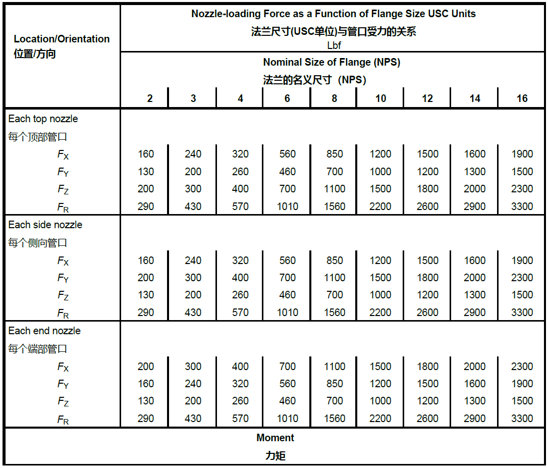
==Table 5 Nozzle Loadings==
==表5—管口受力==
::: tip
(解释:本表为美制单位)
:::
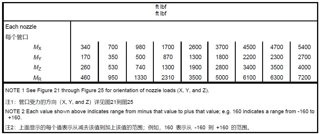
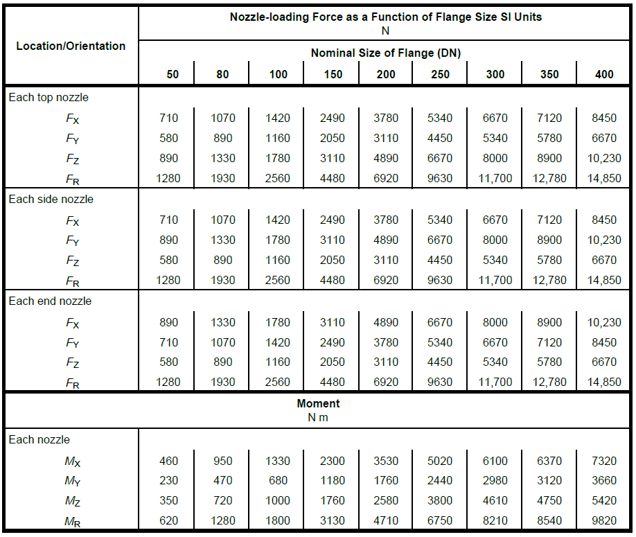
==Table 5 Nozzle Loadings (Continued)==
==图5—管口受力(续表)==
::: tip
解释:本表与上表仅是单位不一样,这个表示SI单位制。不再赘述
:::
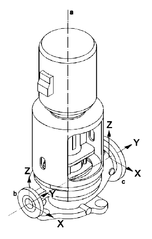 a Shaft centerline.轴中心线
b Discharge.排出口
c Suction.吸入口
a Shaft centerline.轴中心线
b Discharge.排出口
c Suction.吸入口
==Figure 21 Coordinate System for the Forces and Moments in Table 5, Vertical In-line Pumps==
==图21—立式管道泵的力和力矩的坐标系统==
 Key(关键点)
1 discharge nozzle(排出口)
2 suction nozzle(吸入口)
3 center of pump(泵中心)
a Shaft centerline.(轴线)
b Pedestal centerline.(支撑中心线)
c Vertical plane.(竖直面)
Key(关键点)
1 discharge nozzle(排出口)
2 suction nozzle(吸入口)
3 center of pump(泵中心)
a Shaft centerline.(轴线)
b Pedestal centerline.(支撑中心线)
c Vertical plane.(竖直面)
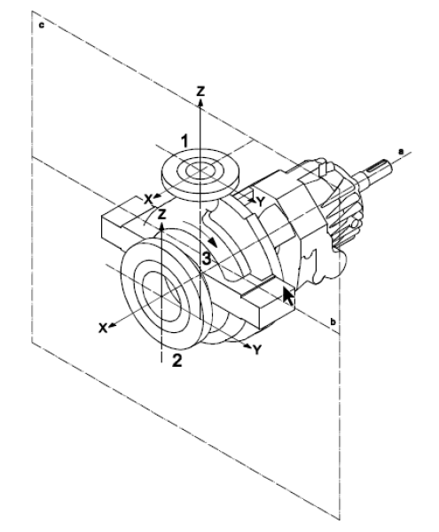
==Figure 22 Coordinate System for the Forces and Moments in Table 5, Horizontal Pumps with End Suction and Top Discharge Nozzles==
==图22—端进顶出水平泵的力和力矩的坐标系统==
 Key(关键点)
1 discharge nozzle(排出管口)
2 suction nozzle(吸入管口)
3 center of pump(泵中心)
a Shaft centerline.(轴中心线)
b Pedestal centerline.(支撑中心线)
c Vertical plane.(竖直面)
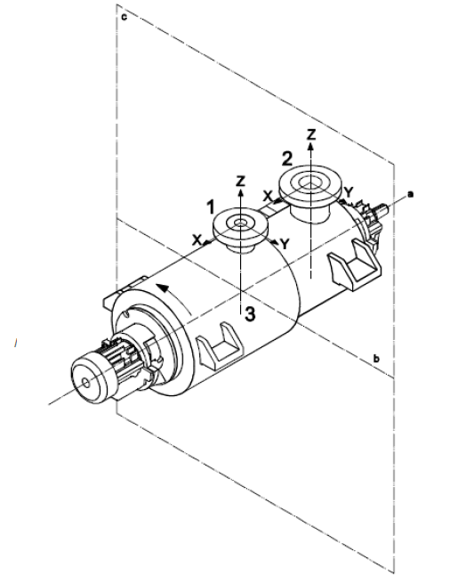
==Figure 23 Coordinate System for the Forces and Moments in Table 5, Horizontal Pumps with Top Nozzles==
==图23 顶出的水平泵的力和力矩坐标系统==
Key(关键点)
1 discharge nozzle(排出管口)
2 suction nozzle(吸入管口)
3 center of pump(泵中心)
a Shaft centerline.(轴中心线)
b Pedestal centerline.(支撑中心线)
c Vertical plane.(竖直面)
==Figure 23 Coordinate System for the Forces and Moments in Table 5, Horizontal Pumps with Top Nozzles==
==图23 顶出的水平泵的力和力矩坐标系统==
 Key(关键点)
1 discharge nozzle(排出管口)
2 suction nozzle(吸入管口)
3 center of pump*(泵中心)
a Shaft centerline.(轴中心线)
b Pedestal centerline.(支撑中心线)
c Vertical plane.(竖直面)
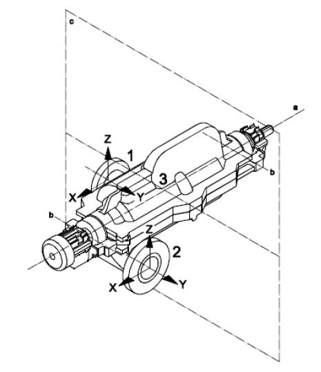
==Figure 24 Coordinate System for the Forces and Moments in Table 5, Horizontal Pumps with Side Suction and Side Discharge Nozzles==
==图24 侧吸侧排的水平泵的力和力矩坐标系统==
Key(关键点)
1 discharge nozzle(排出管口)
2 suction nozzle(吸入管口)
3 center of pump*(泵中心)
a Shaft centerline.(轴中心线)
b Pedestal centerline.(支撑中心线)
c Vertical plane.(竖直面)
==Figure 24 Coordinate System for the Forces and Moments in Table 5, Horizontal Pumps with Side Suction and Side Discharge Nozzles==
==图24 侧吸侧排的水平泵的力和力矩坐标系统==
 a Shaft centerline.(轴线)
b Discharge.(排出口)
c Suction.(吸入口)
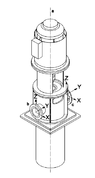
==Figure 25 Coordinate System for the Forces and Moments in Table 5, Vertically Suspended, Double-casing Pumps==
==图25 立式悬吊泵,双泵壳泵的力和力矩的坐标系统==
a Shaft centerline.(轴线)
b Discharge.(排出口)
c Suction.(吸入口)
==Figure 25 Coordinate System for the Forces and Moments in Table 5, Vertically Suspended, Double-casing Pumps==
==图25 立式悬吊泵,双泵壳泵的力和力矩的坐标系统==