6.4.1 Casing Opening Sizes壳体开孔尺寸
6.4.1.1 Openings for nozzles and other pressure casing connections shall be standard pipe sizes. Openings of nominal pipe size (NPS) 11/4, NPS 21/2, NPS 31/2, NPS 5, NPS 7, and NPS 9 [diameter nominal (DN) 32, DN 65, DN 90, DN 125, DN 175, and DN 225] shall not be used.
管口和承压壳体的接口都应该是标准的管子尺寸。不应该使用名义管径为(NPS) 11/4, NPS 21/2, NPS 31/2, NPS 5, NPS 7, 和NPS 9 [名义直径为 (DN) 32, DN 65, DN 90, DN 125, DN 175, and DN 225] 。
::: tip
解释:这些管径的管子都不是常用系列。
:::
6.4.1.2 Casing connections other than suction and discharge nozzles shall be at least NPS 1/2 (DN 15) for pumps with discharge nozzle openings NPS 2 (DN 50) and smaller. Connections shall be at least NPS 3/4 (DN 20) for pumps with discharge nozzle openings NPS 3 (DN 80) and larger, except that connections for seal flush piping and gauges may be NPS 1/2 (DN 15) regardless of pump size.
除了进出口管口外,对于排出口开孔小于等于NPS 2 (DN 50)的泵,其壳体的接口都至少是 NPS 1/2 (DN 15) 的。对于排出口开孔大于等于NPS 3 (DN 80)的泵,其壳体的接口都至少是NPS 3/4 (DN 20) 的(除了密封冲洗管路和仪表管路,它们可能无论泵大小都是NPS 1/2 (DN 15))。
::: tip
解释:很多厂家的泵,即使其出口是DN80的,但是它的排凝口很多都是DN15的,这样不方便泵体液体的充分排净。
:::
6.4.2 Casing Nozzle Connections壳体管口连接
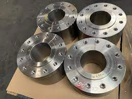
6.4.2.1 All casing connection nozzles shall be flanged, except for the seal gland connection, or those on pumps with forged casings, which shall be flanged or machined and studded. One- and two-stage pumps shall have suction and discharge flanges of equal rating. If the pump is supplied with machined and studded connections, the pump vendor shall provide drawings showing the dimensions of break-out spool pieces to allow the pump to be conveniently removed from the piping. Spool pieces shall be provided by the purchaser.
除了密封格兰的接口或者锻造泵壳的泵接口(锻造泵壳的泵接口可以是法兰或者是加工栽丝的),所有泵壳的连接管口都应该是法兰的。一级和两级泵的吸入口和排出口应该有相同的等级。如果所提供的泵带有加工栽丝连接,则泵供应商应提供图纸,说明拆卸管段的尺寸,以便于将泵从管道上拆卸下来。管段部件应由买方提供。
::: tip
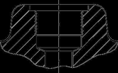
解释:所有的泵壳连接口,指的是对外的接口。BB5泵的外筒体是锻件,其出入口可以是加工栽丝machined and studded的,加工和栽丝的意思如下图,就是加工一个平面,平面上钻孔,用螺柱将法兰与下图的螺纹连接。此处就要求了1或2级泵的吸入口和排出口应该有相同的等级,工程实际中往往要求所有泵的进出口压力等级保持一致。加工栽丝machined and studded如下图
 Break-out spool pieces就是我们常用的检修短节,用于方便检修
:::
Break-out spool pieces就是我们常用的检修短节,用于方便检修
:::
NOTE Break-out spool pieces eliminate the requirement to remove large sections of piping in order to take the pump casing out during major overhauls.
注:在大修期间,有了检修短节,则拆卸管段时无需拆卸大段管道就可以取出泵壳。
6.4.2.2 All nozzle flanges shall conform to the pressure ratings and dimensional requirements of ASME B16.5 and ASME B16.47 Series B, except as noted in 6.4.2.2.1, 6.4.2.2.2, 6.4.2.3, and 6.4.2.4.
所有管口法兰应该满足ASME B16.5和ASME B16.47系列B中的压力等级和尺寸的要求,6.4.2.2.1, 6.4.2.2.2, 6.4.2.3, 和6.4.2.4说明的除外。
::: tip
解释:ASME B16.5的最大法兰直径到DN600,DN600以上的法兰需要执行ASME B 16.47
:::
NOTE For the purpose of this standard, ISO 7005-1 and EN 1759.1 are equivalent to ASME B16.5 and ASME B16.47.
注:就本标准而言, ISO 7005-1 和 EN 1759.1 与 ASME B16.5 和 ASME B16.47等效.
6.4.2.2.1 For ASME B16.5 flange sizes from 1/2 NPS (12 mm) to 10 NPS (250 mm), the actual outside diameters (ODs) of the flanges shall be not less than their nominal OD minus 0.16 in. (4 mm). For ASME B16.5 flange sizes from 12 NPS (300 mm) to 24 NPS (600 mm), the actual ODs of the flanges shall be not less than their nominal OD minus 0.21 in. (5 mm).
对于尺寸从1/2 NPS (12 mm)到10 NPS (250 mm)的ASME B16.5的法兰来说,法兰的实际外径(ODs) 应该不小于他们的名义OD减去 0.16 in. (4 mm)。对于尺寸从12 NPS (300 mm) 到 24 NPS (600 mm)的ASME B16.5的法兰来说,法兰的实际外径(ODs) 应该不小于他们的名义外径OD减去0.21 in. (5 mm)。
::: tip
解释:这就是法兰的允许加工误差。
:::
NOTE These tolerances are consistent with the negative tolerances stated on EN 1092-1, Table 22.
注:这些允差与 EN 1092-1 表 22 中规定的负公差一致。
6.4.2.2.2 For ASME B16.47 flanges, the actual ODs of the flanges shall be not less than their nominal OD minus 0.25 in. (6 mm).
对于ASME B16.47的法兰,法兰实际实际外径应该不小于他们名义外径减去0.25 in. (6 mm)
6.4.2.3 Flanges in all materials that are thicker or have a larger OD than required by the relevant ISO or ASME standards in this standard are acceptable. Nonstandard (oversized) flanges shall be completely dimensioned on the arrangement drawing. If nonstandard flanges require studs or bolts of nonstandard length, this requirement shall be identified on the arrangement drawing.
所有材料的法兰,如果其厚度或外径大于本标准中相关 ISO 或 ASME 标准的要求,均可接受。非标准(超大)法兰应在布置图上标明完整尺寸。如果非标准法兰需要非标准长度的螺柱或螺栓,则应在布置图上也标明这一要求。
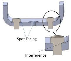
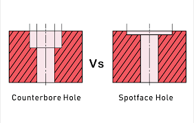
6.4.2.4 Flanges shall be full faced or spot faced on the back and shall be designed for through bolting, except for jacketed casings. If nonstandard stud lengths are required for extra-thick flanges, the vendor shall provide studs of the appropriate length.
法兰背面应为全面(full faced)或点状面(spot faced),并应设计成可通过螺栓拧紧,夹套泵壳除外。如果超厚法兰需要非标准长度的螺柱,供应商应提供适当长度的螺柱。
::: tip
解释:Spot face见下图
 :::
:::
6.4.2.5 To minimize nozzle loading and facilitate installation of piping, machined faces of pump flanges shall be parallel to the plane of the flange as shown on the general arrangement drawing within 0.5°. Bolt holes or studs shall straddle centerlines parallel to the main axes of the pump.
为尽量减少管口载荷并方便管道安装,泵法兰的加工面应与总布置图上所示的法兰平面平行,误差不得超过 0.5°。螺栓孔或螺柱孔中心线应与泵主轴中心线平行。
::: tip
解释:说明了实际法兰平面与图纸平面的误差.
:::
6.4.2.6 Connections, including gusseting, welded to the casing (up to the first flange) shall meet or exceed the material and the pressure-temperature requirements of the casing, including impact values, rather than the requirements of the connected piping. For C6 construction, 316L piping and fittings are required for process temperatures up to and including 500 °F (260 °C), above which UNS N06625 materials shall be used. Gussets shall be a minimum of 316L in either case.
焊接到泵壳上的接管(直到第一个法兰),包括支撑,应满足或超过泵壳的材料和压力-温度要求,包括冲击值,而不是要符合连接管道的要求。对于 C6 结构,工艺温度在 500 °F (260 °C)以下(含 500 °F)时需要使用 316L 管道和管件,超过 500 °F (260 °C)时应使用 UNS N06625 材料。在这两种情况下,支撑都必须至少为 316L。
::: tip
解释:本条是12版的新增内容,本条要求了焊接在泵壳上接管的要求,C6材质的是12Cr%的材质,而对应的没有12Cr%的无缝钢管,因此对于泵壳排凝口管线的材质,之前都用碳钢(降低材质)或者304(升高材质)的,这次有了明确要求。
:::
6.4.2.7 All connection welding shall be completed before the casing is hydrostatically tested (see 8.3.2).
所有接口处的焊接必须在泵壳进行水压试验之前完成(见 8.3.2)
6.4.2.8 All connections shall be suitable for the hydrostatic test pressure of the region of the casing to which they are attached.
所有接口均应适用于所连接泵壳区域的静水压力试验。
::: tip
解释:水压试验必须带着这些接管一起试验,因为他们都是按照MAWP设计的。
:::
6.4.2.9 All of the purchaser's connections shall be accessible for disassembly without requiring the pump, or any major part of the pump, to be moved.
买方的所有接口处均应便于拆卸,而无需移动泵或泵的任何主要部分。
6.4.3 Auxiliary Connections附属连接
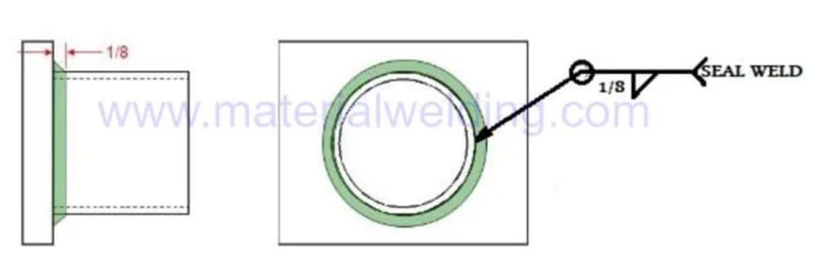
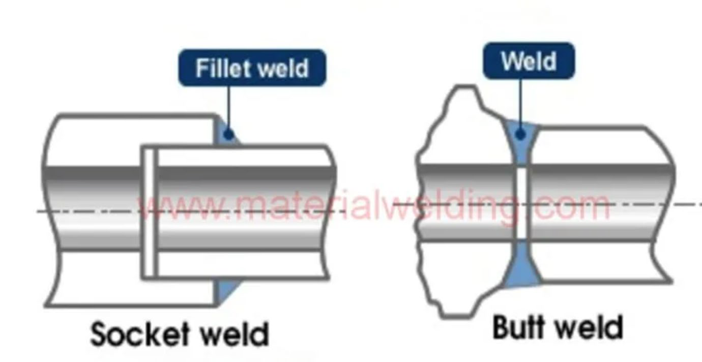
6.4.3.1 Auxiliary connections shall be integrally flanged, socket welded, or butt welded as specified by the purchaser. Seal welding of threaded connections is not permitted.
辅助连接应采用法兰、承插焊或买方规定的对焊。不允许对螺纹连接进行密封焊接。
::: tip
解释:seal weld就是密封焊,如下图
 承插焊(socket welded)和对焊(butt welded)如下图所示
 :::
:::
6.4.3.2 If specified, for pumps in pipeline service with a maximum operating temperature of 130 °F (55 °C) or less, auxiliary connections may be threaded. Threaded openings shall be tapered threads in accordance with ASME B1.20.1 or ISO 7-1 or alternatively cylindrical threads in accordance with ISO 228-1. Cylindrical threads shall be sealed with a contained face gasket of suitable material sealing to a machined face (see Figure 19). The chosen method and details of threaded connection shall be approved by the purchaser. Where possible, threaded connections shall be brought to a remote flange that can be disassembled for maintenance so as to require the least amount of assembly/disassembly of the threaded connection.
对于最高工作温度不超过 55°C (130 °F) 的管线泵,如果有规定,辅助接口可以是螺纹连接。螺纹开口应为符合 ASME B1.20.1 或 ISO 7-1 标准的锥形螺纹,或符合 ISO 228-1 标准的圆柱形螺纹。圆柱形螺纹必须用适当材料制成的密封面垫片与加工面来进行密封(见图 19)。所选择的螺纹连接方法和细节必须经买方批准。在可能的情况下,应将螺纹连接带至可拆卸维护的远方法兰上,以尽量减少螺纹连接的装配/拆卸工作量。
::: tip
解释:pipeline service一般指的是长输管线工况。
在可能的情况下,应将螺纹连接带至可拆卸维护的远方法兰上,以尽量减少螺纹连接的装配/拆卸工作量。这句话的意思是,可以螺纹连接,但是螺纹连接后的管道应该再接一个法兰,以后拆卸时,只拆卸法兰,不拆螺纹。
:::
NOTE 1 Threaded connections on pressure-containing parts are prone to leakage.
注1:承压部件上的螺纹连接容易发生泄漏
NOTE 2 Tapered threads create a seal by deformation of threads or use of a suitable thread sealant. They are prone to leakage if under-torqued and prone to thread damage if overtorqued.
注2:锥形螺纹通过螺纹变形或使用合适的螺纹密封剂来形成密封。如果扭矩不足,则容易发生泄漏;如果扭矩过大,则容易损坏螺纹。
NOTE 3 Cylindrical threads with a face gasket require suitable gasket material and are prone to leakage due to under- torque (inadequate gasket compression) or overtorque (extruding of the gasket). Surface finish and condition of the gasket mating faces are critical for proper sealing.
带面垫片的圆柱螺纹需要合适的垫片材料,并且容易因扭矩不足(垫片压缩不充分)或扭矩过大(垫片挤出)而发生泄漏。垫片配合面的表面光洁度和状态对于正确密封至关重要。
==Figure 19 Machined Face Suitable for Gasket Containment if Using Cylindrical Threads==
==图19 如果使用圆柱形螺纹,机加工面适用于垫片封装==
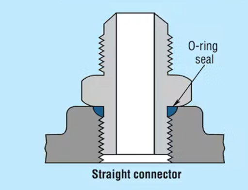
6.4.3.3 If specified, special threaded fittings for transitioning from the casing to tubing for seal flush piping may be used provided that a secondary sealing feature, such as O-rings, are used and that the joint does not depend on the thread contact alone to seal the fluid. The connection boss shall have a machined face suitable for sealing contact.
如果有规定,可使用特殊的螺纹接头从泵壳过渡到密封冲洗管道的管子,但必须使用辅助密封功能,如 O 形圈,而且接头不能仅靠螺纹接触来密封流体。连接凸缘应具有适合密封接触的加工面。
::: tip
解释:带有O 形圈的螺纹
 :::
:::
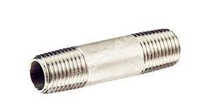
6.4.3.4 The first segment of piping connected to the casing shall not be more than 6 in. (150 mm) long and shall be a minimum of schedule 160 seamless for pipe sizes NPS 1 (DN 25) and smaller and a minimum of schedule 80 for pipe sizes NPS 11/2 (DN 40) and larger. The first segment of piping (nipple) shall be straight, if practical, to allow connections such as drains to be cleaned. The first segment can attach axially to avoid increasing centerline height (see 7.4.5). On small pumps, if this causes interference with the suction nozzle, for example, this requirement is considered impractical.
连接到泵壳的第一段管道长度不得超过 6 英寸 (150 mm),对于 NPS 1 (DN 25) 及更小的管道,最小应为 160 schedule的无缝管,对于 NPS 11/2 (DN 40) 及更大的管道,最小应为 80schedule的无缝管。在可行的情况下,第一段管道(接头)应是直的,以便清洁排水管等连接处。第一段管道可以轴向连接,以避免增加中心线高度(见 7.4.5)。在小型泵上,如果这会对吸入口等造成干涉,则认为此要求不切实际。
::: tip
解释:之所以要求连接到泵壳的的辅助接口的第一段管道长度和管道壁厚,是为了保证这段管线和泵体的刚度。但是实际中,泵厂的排凝管道与泵体往往是承插焊接的,排凝管的长度往往都大于150mm。
piping nipple管接头如下图所示。
 :::
:::
6.4.3.5 Threaded openings, which are allowed in seal glands and in pump casings for some pipeline services (if specified in 6.4.3.2), shall be plugged. Plugs for tapered threads shall be long-shank solid round- head, or long-shank hexagon-head, bar stock plugs in accordance with ASME B16.11. Plugs for cylindrical threads shall be solid hexagon-head plugs in accordance with DIN 910. These plugs shall meet the material requirements of the casing. A lubricant/sealant that is suitable for high-temperature duty shall be used to ensure that the threads are vapor-tight. Plastic plugs are not permitted.
某些管线场合(如 6.4.3.2 中的规定)的密封格兰和泵壳允许有螺纹开口,但必须堵塞。用于锥形螺纹的塞子必须是符合 ASME B16.11 标准的长柄实心圆头塞子或长柄六角头塞子。圆柱螺纹堵头必须是符合 DIN 910 标准的实心六角头堵头。这些塞子应符合泵壳的材料要求。高温工况时,必须使用适合高温工作的润滑剂/密封剂,以确保螺纹的气密性。不允许使用塑料塞子。
::: tip
解释:管线工况的锥螺纹(tapered threads),要用特定的塞子塞住。不得使用塑料塞子。
:::
6.4.3.6 If specified, auxiliary connections to the pressure casing shall be machined and studded. These connections shall conform to the facing and drilling requirements of 6.4.2.2. Studs and nuts shall be furnished installed. If the stud engagement does not control the depth of the threads in the mating hole, the first 1.5 threads at both ends of the stud shall be removed.
如果有规定,与泵壳的辅助连接必须是加工栽丝的形式。这些连接件必须符合 6.4.2.2 的端面和钻孔要求。螺柱和螺母必须安装到位。如果螺柱咬合不能控制配合孔中的螺纹深度,则必须去除螺柱两端的前 1.5 个螺纹。
::: tip
解释:为了保证螺栓的螺纹插入孔的深度在合理的范围内,需要根据孔的深度和螺栓的长度,调整螺栓的螺纹数量,去掉多余的螺纹,使螺栓和孔的螺纹能够有效地配合。
:::
6.4.3.7 All pumps shall be provided with vent and drain connections, except that vent connections may be omitted if the pump is made self-venting by the arrangement of the nozzles. Pumps that are not self-venting shall be provided with vent connections in the pressure casing, as required (see 6.8.10). If the pump cannot be completely drained for geometrical reasons, this shall be stated in the proposal. The operating manual shall include a drawing indicating the quantity and location(s) of the liquid remaining in the pump.
所有泵都必须有排气和排液接口,但如果泵通过管口的布置实现了自排气,则可省去排气接口。非自排气的泵应按要求在承压泵壳内设置排气接口(见 6.8.10)。如果泵因几何原因无法完全排液,则应在建议书中说明。操作手册应包括一张图纸,标明泵内残留液体的数量和位置。
::: tip
解释:大多数泵都可以做成自排气的,但是立式高速泵,BB1,有些BB2,BB3泵大多需要排气口。所有泵都有排液口,但是有些BB2泵,BB4的泵,BB5的泵很多都无法完全排净,这是因为腔室太多。
:::
NOTE As a guide, a pump is considered functionally self-venting if the nozzle arrangement and the casing configuration permit sufficient venting of gases from the first-stage impeller and volute area to prevent loss of prime during the starting sequence.
注:作为指导,如果管口布置和泵壳结构允许从第一级叶轮和涡壳区域充分排放气体,以防止在失去自吸功能,则可认为泵具有自排气功能。
::: tip
解释:prime是自吸的意思。这里的自吸,不是自吸泵,而是叶轮把液体抽走形成真空,后面的液体自动补上。
:::
6.4.3.8 A process compatible thread lubricant of proper temperature specification shall be used on all threaded connections. Thread tape shall not be used.
所有螺纹连接都必须使用温度规格适当的、工艺兼容的螺纹润滑剂。不得使用螺纹胶带。
::: tip
解释:螺纹润滑剂可以降低螺纹的摩擦、磨损和腐蚀,提高螺纹的密封性和承压能力。thread tape是一种用于密封螺纹连接的物质就是我们常说的生胶带,由聚四氟乙烯或其他塑料制成的薄带,可以缠绕在螺纹的外部,填充螺纹的间隙,防止流体的渗漏。thread tape的优点是密封效果好,易于使用和拆卸,而且对温度和化学品的耐受性好。thread tape的缺点是不具有润滑作用,不能减少螺纹的摩擦和磨损,而且容易撕裂和断裂,导致螺纹的损坏和堵塞。
:::
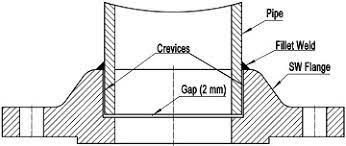
6.4.3.9 For socket-welded construction, there shall be a 1/16 in. (1.5 mm) gap between the pipe end and bottom of the socket before welding.
对于承插焊结构,在焊接前,管端与承插口底部之间应留有 1/16 英寸 (1.5 mm) 的间隙。
::: tip
解释:留下这个间隙的原因是,防止因为焊接时的热膨胀导致承插结构损坏。就是下图中的2mm的位置
 :::
:::
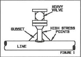
6.4.3.10 Piping NPS 1 and smaller shall be gusseted in two orthogonal planes to increase the rigidity of the piped connection, in accordance with the following stipulations, except connections for seal flush piping and gauges.
NPS 1 及更小的管道必须按照以下规定,在两个正交平面上支撑,以增加管道连接的刚度,但密封冲洗管道和仪表的连接口除外。
::: tip
解释:现在这一条,很少有厂家能做到。很多泵体的排凝口都悬着。并不加支撑。见下图的gusset,类似于管线的加强筋
 :::
:::
a) Gussets shall be of a material compatible with the pressure casing and the piping and shall be made of either flat bar with a minimum cross section of 1 in. by 0.12 in. (25 mm by 3 mm) or round bar with a minimum diameter of 0.38 in. (9 mm).
支撑的材料必须与承压壳体和管道的材料相匹配,必须由横截面最小为 1 英寸 x 0.12 英寸(25 毫米 x 3 毫米)的扁杆或直径最小为 0.38 英寸(9 毫米)的圆杆制成。
b) Gusset design shall be typically as shown in Figure 20.
支撑的典型设计见图20
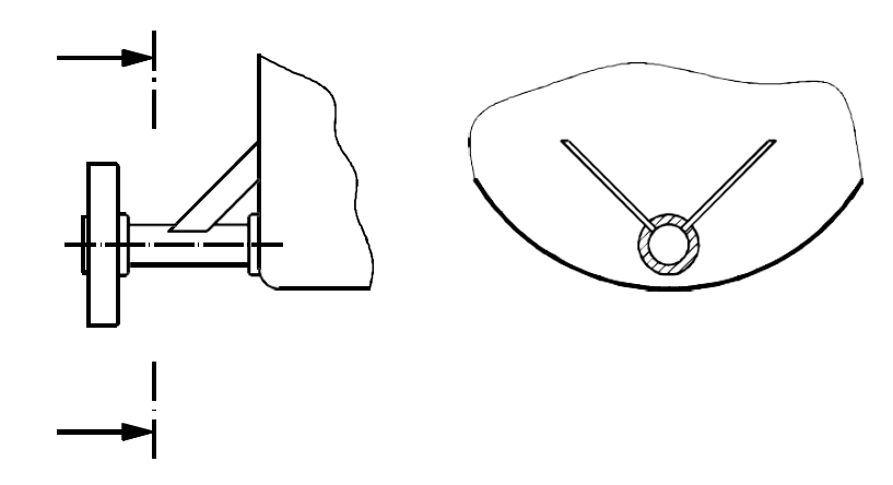
==Figure 20 Typical Gusset Design==
==图20-典型的支撑设计==
c) Gussets shall be located at or near the connection end of the piping and fitted to the closest convenient location on the casing to provide maximum rigidity. The long width of gussets made with bar shall be perpendicular to the pipe and shall be located to avoid interference with the flange bolting or any maintenance areas on the pump.
支撑应位于或靠近管道的连接端,并安装在壳体上最方便的位置,以提供最大的刚度。用钢筋制作的支撑的长宽应与管道垂直,其位置应避免与法兰螺栓或泵上任何维护区域相干涉。
d) Gusset welding shall meet the fabrication requirements (see 6.12.3), including postweld heat treatment (PWHT) when required, and the inspection requirements (see 8.2.2) of this standard.
支撑焊接应符合本标准的制造要求(见 6.12.3),包括焊后热处理(PWHT)(如需要)和检查要求(见 8.2.2)。
e) Gussets may also be bolted to the casing if drilling and tapping is done prior to hydrostatic test. Proposals to use clamped or bolted gusset designs shall be submitted to the purchaser for approval.
如果在水压试验前进行钻孔和攻丝,也可以用螺栓将支撑固定在泵壳上。使用夹紧式或螺栓固定式支撑设计的方案应提交买方批准。
::: tip
解释:还是使用焊接比较方便。
:::