F.1 Horizontal Pumps水平泵
F.1.1 Acceptable piping configurations should not cause excessive misalignment between the pump and driver. Piping configurations that produce component nozzle loads lying within the ranges specified in Table 5 limit casing distortion to one-half the pump vendor's design criterion (see 6.3.3) and ensure pump shaft displacement of less than 0.010 in. (250 μm).
可接受的管道配置不应造成泵和驱动器之间的过度不对中。管道布置产生的部件管口载荷应在表 5 规定的范围内,将外壳变形限制在泵供应商设计标准的二分之一(见 6.3.3),并确保泵轴位移小于 0.010 英寸(250 微米)。
F.1.2 Piping configurations that produce loads outside the ranges specified in Table 5 are also acceptable without consultation with the pump vendor if the conditions specified in F.1.2 a) through F.1.2 c) as follows are satisfied. Satisfying these conditions ensures that any pump casing distortion is within the vendor's design criteria (see 6.3.3) and that the displacement of the pump shaft is less than 0.015 in. (380 μm).
如果满足下列 F.1.2 a) 至 F.1.2 c) 中规定的条件,也可以接受产生表 5 规定范围之外负载的管道布置,而无需与泵供应商协商。满足这些条件可确保任何泵壳变形都在供应商的设计标准 (见 6.3.3)范围内,并且泵轴的位移小于 0.015 英寸 (380 微米)。
a) The individual component forces and moments acting on each pump nozzle flange shall not exceed the range specified in Table 5 (T4) by a factor of more than 2.
作用在每个泵管口法兰上的单个分力和力矩不得超过表 5(T4)规定范围的 2 倍以上。
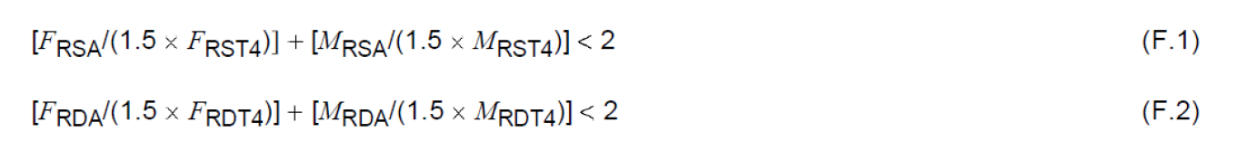
b) The resultant applied force (FRSA, FRDA) and the resultant applied moment (MRSA, MRDA) acting on each pump-nozzle flange shall satisfy the appropriate interaction equations as given in Equations (F.1) and (F.2):
作用在每个泵-管口法兰上的合外力(FRSA、FRDA)和合外力矩(MRSA、MRDA)必须满足公式 (F.1) 和 (F.2) 中给出的相应相互作用方程:
- c) The applied component forces and moments acting on each pump nozzle flange shall be translated to the center of the pump. The magnitude of the resultant applied force, FRCA, the resultant applied moment, MRCA, and the applied moment shall be limited by Equations (F.3) to (F.5). (The sign convention shown in Figure 21, Figure 22, Figure 23, Figure 24, and Figure 25 and the right-hand rule should be used in evaluating these equations.)
作用在每个泵管口法兰上的外加力和外加力矩应转换到泵的中心。合作用力 FRCA、合作用力矩 MRCA 和作用力矩的大小应受公式 (F.3) 至 (F.5) 的限制。(在计算这些公式时,应使用图 21、图 22、图 23、图 24 和图 25 所示的符号约定和右手定则)。
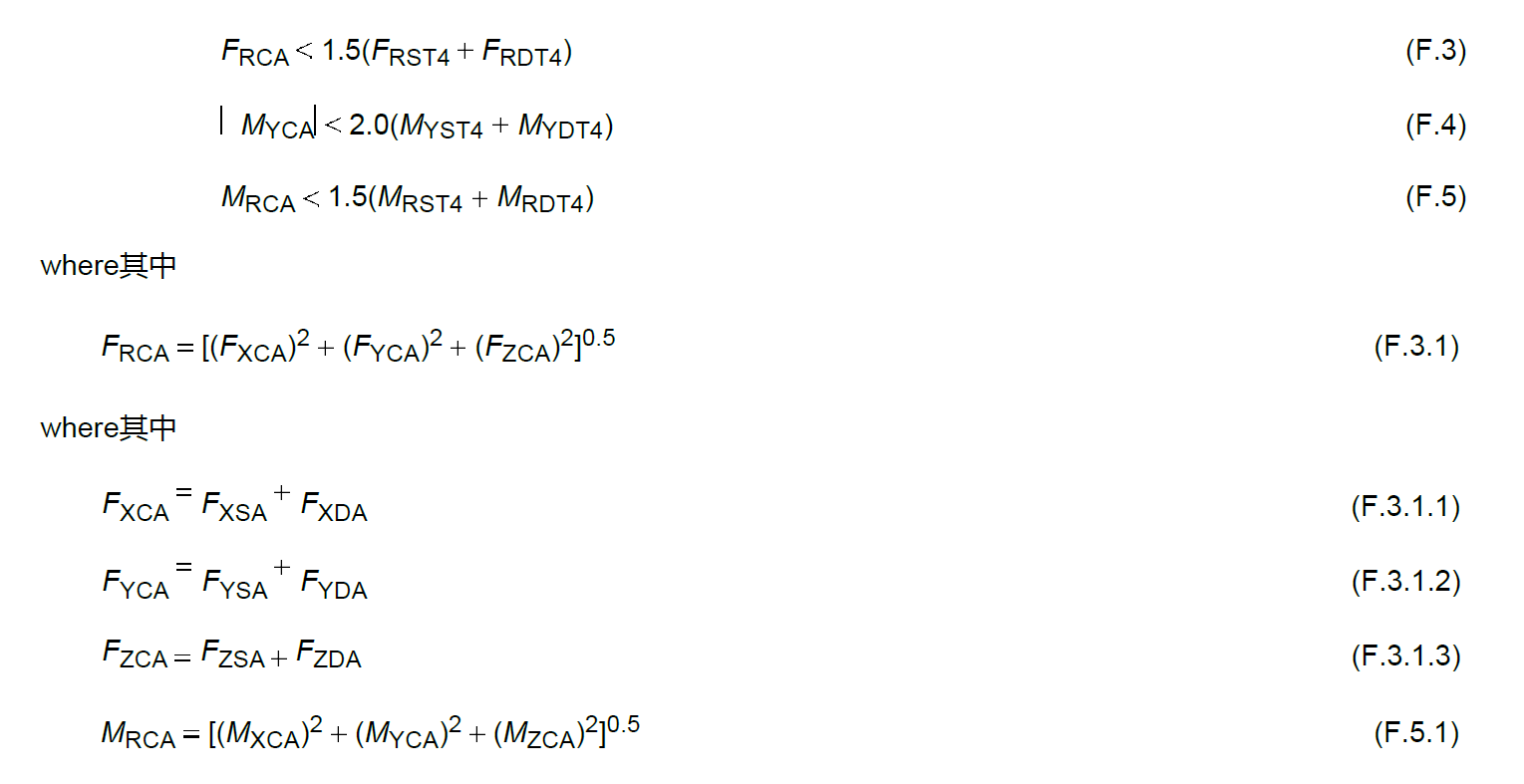
其中
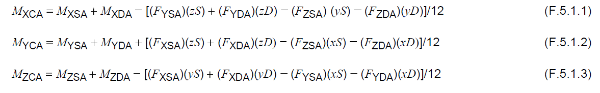
In SI units, the constant 12 shall be changed to 1000. This constant is the conversion factor to change inches to feet or millimeters to meters.
在国际单位制中,常数 12 应改为 1000。该常数是将英寸转换为英尺或将毫米转换为米的转换系数。
F.1.3 Piping configurations that produce loads greater than those allowed in F.1.2 shall be approved by the purchaser and the vendor. To evaluate the actual machine distortion (at ambient conditions), the piping alignment checks required in API 686:2009, Chapter 6, should be performed.
如果管道配置产生的负载大于 F.1.2 中允许的负载,则应获得买方和卖方的批准。为评估机器实际变形(在环境条件下),应执行 API 686:2009 第 6 章中要求的管道对准检查。
NOTE API 686 allows only a small fraction of the permitted distortion resulting from use of the values from this annex.
注: API 686只允许使用本附录中的数值所导致的允许变形的很小一部分。
F.2 Vertical In-line Pumps立式管道泵
Vertical in-line pumps (OH3 and OH6) that are supported only by the attached piping can be subjected to component piping loads that are more than double the values shown in Table 5 if these loads do not cause a principal stress greater than 5950 psi (41 N/mm2) in either nozzle. For calculation purposes, the section properties of the pump nozzles shall be based on Schedule 40 pipe whose nominal size is equal to that of the appropriate pump nozzle. Equations (F.6), (F.7), and (F.8) can be used to evaluate the principal stress, the longitudinal stress, and the shear stress, respectively, in the nozzles.
仅由附加管道支撑的立式管道泵 (OH3 和 OH6)可承受超过表 5 所示值两倍的管道组件载荷,前提是这些载荷不会导致任一管口的主应力超过 5950 磅 / 平方英寸(41 牛 / 平方毫米)。为便于计算,泵管口的截面特性应基于Schedule 40 管材(其公称尺寸等于相应泵管口尺寸)。公式 (F.6)、(F.7) 和 (F.8) 可用来分别评估管口中的主应力、纵向应力和剪切应力。
For SI units, Equations (F.6) to (F.8) apply:
对于SI制,适用公式F.6到F.8
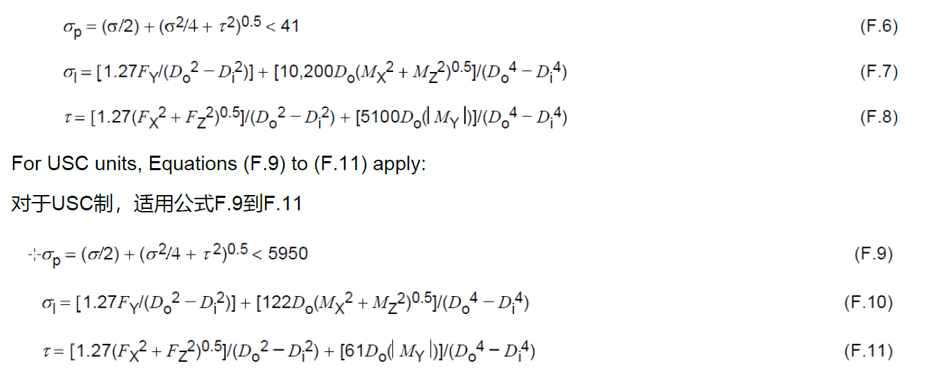
FX, FY, FZ, MX, MY, and MZ represent the applied loads acting on the suction or discharge nozzles, thus subscripts SA and DA have been omitted to simplify the equations. The sign of FY is positive if the load puts the nozzle in tension; the sign is negative if the load puts the nozzle in compression. Reference can be made to Figure 21 and the applied nozzle loads to determine whether the nozzle is in tension or compression. The absolute value of MY should be used in Equations (F.8) and (F.11).
FX、FY、FZ、MX、MY 和 MZ 表示作用在吸入或排出管口上的外加载荷,因此省略了下标 SA 和 DA 以简化方程。如果负载使管口处于拉伸状态,则 FY 的符号为正;如果负载使管口处于压缩状态,则 FY 的符号为负。可参考图 21 和应用的管口载荷来确定管口处于拉伸还是压缩状态。公式 (F.8) 和 (F.11) 中应使用 MY 的绝对值。
F.3 Nomenclature术语
The following definitions apply to the sample problems in F.4.
以下定义适用于 F.4 中的示例问题。
C is the center of the pump. For pump types OH2, BB2, and BB5 with two support pedestals, the center is defined by the intersection of the pump shaft centerline and a vertical plane passing through the center of the two pedestals (see Figure 24 and Figure 25). For pump types BB1, BB3, and BB5 with four support pedestals, the center is defined by the intersection of the pump shaft centerline and a vertical plane passing midway between the four pedestals (see Figure 23);
是泵的中心。对于带有两个支撑基座的 OH2、BB2 和 BB5 型泵,中心由泵轴中心线与穿过两个基座中心的垂直平面的交点确定(见图 24 和图 25)。对于带有四个支撑基座的 BB1、BB3 和 BB5 型泵,中心由泵轴中心线与穿过四个基座中间的垂直平面的交点确定(见图 23);
D is the discharge nozzle;
是排出管口
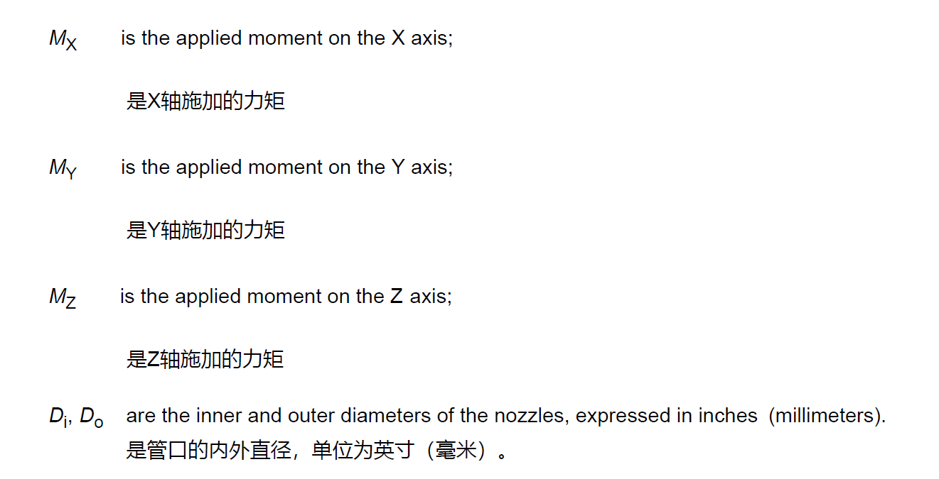
Di is the inside diameter of Schedule 40 pipe whose nominal size is equal to that of the pump nozzle in question, expressed in inches (millimeters);
是名义尺寸与相关泵管口尺寸相同的 Schedule 40 号管材的内径,单位为英寸(毫米);
Do is the OD of Schedule 40 pipe whose nominal size is equal to that of the pump nozzle in question, expressed in inches (millimeters);
是名义尺寸与相关泵管口尺寸相同的 Schedule 40 号管材的外径,单位为英寸(毫米);
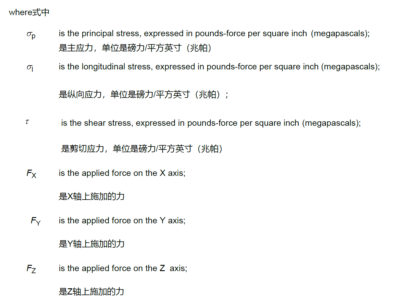
F is the force, expressed in pounds force (newtons);
是力,单位是磅(牛顿)
FR is the resultant force; FRSA and FRDA are calculated by the square root of the sum of the squares method using the applied component forces acting on the nozzle flange; FRST4 and FRDT4 are extracted from Table 5, using the appropriate nozzle size;
是合力;FRSA 和 FRDA 是使用作用在管口法兰上的外加分力,通过平方和的平方根法计算得出的;FRST4 和 FRDT4 是使用适当的管口尺寸,从表 5 中提取的;
M is the moment, expressed in foot-pounds force (newton meters);
是力矩,以英尺磅力(牛顿米)表示;
MR is the resultant moment; MRSA and MRDA are calculated by the square root of the squares method using the applied component moments acting on the nozzle flange; MRST4 and MRDT4 are extracted from Table 5 using the appropriate nozzle size;
是合力矩;MRSA 和 MRDA 是使用作用在管口法兰上的外加分量力矩,通过平方根法计算得出的;MRST4 和 MRDT4 是使用适当的管口尺寸,从表 5 中提取的;
l is the longitudinal stress, expressed in pounds per square inch (newtons per square millimeter);
是纵向应力,单位为磅/平方英寸(牛顿/平方毫米);
p is the principal stress, expressed in pounds force per square inch (megapascals);
是主应力,单位是磅力/平方英寸(兆帕);
is the shear stress, expressed in pounds per square inch (newtons per square millimeter);
是剪应力,单位为磅/平方英寸(牛顿/平方毫米);
S is the suction nozzle;
是吸入管口
x, y, z are the location coordinates of the nozzle flanges with respect to the center of the pump, expressed in inches (millimeters);
是管口法兰相对于泵中心的位置坐标,单位为英寸(毫米);
X, Y, Z are the directions of the load (see Figure 21, Figure 22, Figure 23, Figure 24, and Figure 25);
是负载的方向(见图 21、图 22、图 23、图 24 和图 25);
Subscript A is an applied load;
下标 A 表示外加载荷;
Subscript T4 is a load extracted from Table 5.
下标 T4 是从表 5 中提取的载荷。
F.4 Sample Problems 问题举例
F.4.1 Example 1A SI Units例子1A—SI单位制
F.4.1.1 Problem问题
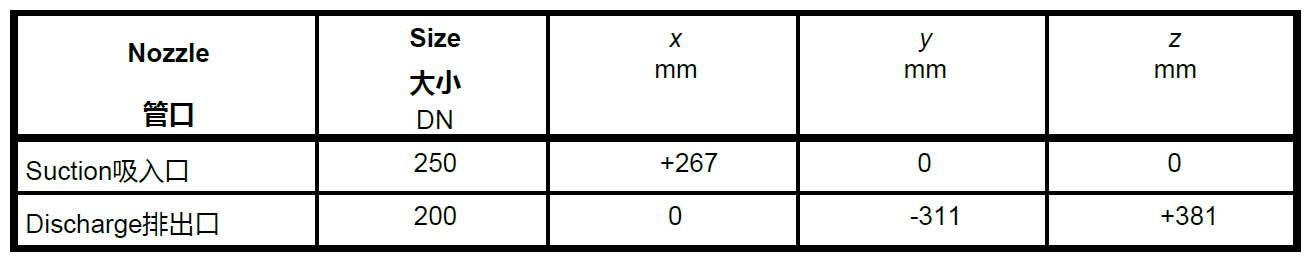
For an overhung-end suction process pump (OH2), the nozzle sizes and location coordinates are as given in Table F.1. The applied nozzle loadings are as given in Table F.2. The problem is to determine whether the conditions specified in F.1.2 a), F.1.2 b), and F.1.2 c) are satisfied.
对于一个悬臂,端吸的泵OH2,管口尺寸和位置坐标表示在表F.1上。施加的管口载荷在表F.2中。该问题是确定是否满足F.1.2 a), F.1.2 b), 和 F.1.2 c) 的工况
F.4.1.2 Solution解决方法
F.4.1.2.1 A check of condition F.1.2 a) is as follows.
检查F.1.2a的工况如下
For the DN 250 end suction nozzle:
对于DN25端吸管口
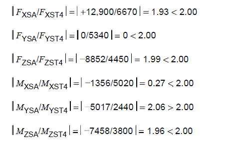
Since MYSA exceeds the value specified in Table 5 (SI units) by more than a factor of 2, it is not satisfactory. Assume that MYSA can be reduced to -4879. Then,
由于 MYSA 超过表 5 中规定值(SI 单位)的 2 倍多,因此不能令人满意。假设 MYSA 可以减小到 -4879。那么
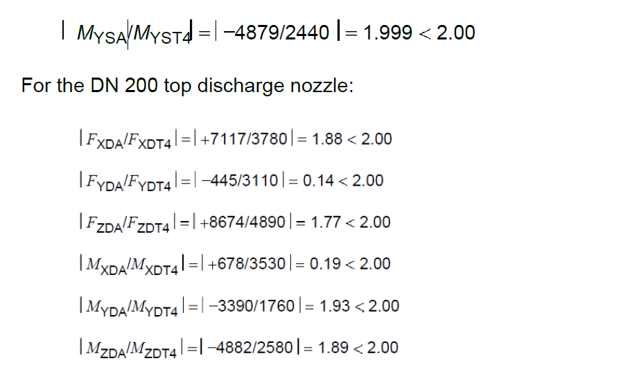
Provided that MYSA can be reduced to -4879, the applied piping loads acting on each nozzle satisfy the condition specified in F.1.2 a).
只要 MYSA 可以减小到 -4879,作用在每个管口上的管道荷载就可以满足 F.1.2 a) 中规定的条件。
==Table F.1 Nozzle Sizes and Location Coordinates for Example 1A==
==表F.1—例子1A中的管口大小合位置坐标==
==Table F.2 Applied Nozzle Loadings for Example 1A==
==表F.2—例子1A中的管口施加载荷==
