C.1 General一般
This annex applies to hydraulic power recovery turbines (HPRTs).
本附录适用于水力能量回收透平(HPRT)。
Power recovery is generally achieved by the reduction of liquid pressure, sometimes with a contribution from vapor or gas evolution during the pressure reduction. A HPRT may be a pump operated with reverse flow.
功率回收通常是通过降低液体压力来实现的,有时在降低压力的过程中还会产生蒸汽或气体。HPRT 可以是反向流动的泵。
C.2 Terminology术语
This standard uses terms that need to be changed or ignored if the standard is applied to HPRTs. The direction of flow through the HPRT is the reverse of that through the pump. In such a context, the word ”pump” may be interpreted as meaning “HPRT ”, the term “pump suction” should be interpreted as meaning the “HPRT outlet”, and the term “pump discharge” should be interpreted as meaning the “HPRT inlet”.
如果该标准适用于 HPRT,则需要更改或忽略该标准使用的术语。流经 HPRT 的方向与流经泵的方向相反。在这种情况下,"泵 "一词可解释为 "HPRT","泵吸入 "一词应解释为 "HPRT 出口","泵排出 "一词应解释为 "HPRT 入口"。
C.3 Design设计
C.3.1 Liquid Characteristics液体特性
C.3.1.1 The purchaser shall advise the HPRT manufacturer whether any portion of the process stream entering the HPRT can flash to vapor and whether absorbed gas in the stream can evolve at any pressure less than the inlet pressure.
买方应告知 HPRT 制造商,进入 HPRT 的工艺流中是否有任何部分会闪蒸成蒸汽,以及工艺流中的吸收气体是否会在任何压力低于入口压力的情况下挥发析出。
::: tip
解释:如果使用了HPRT,液体从高压状态到低压装置,可能会闪蒸出气体,气体会比液体更快的驱动叶轮,发出的功率会更大,超速的可能性更大。因此必须明确液体的特性。
:::
C.3.1.2 The purchaser shall specify the volume percentage of vapor or gas, or both, at the turbine outlet and the pressure and temperature at which the vapor can flash off.
买方应说明透平出口处蒸汽或气体或两者的体积百分比,以及蒸汽闪蒸时的压力和温度。
If known, the liquid composition, and the liquid and vapor (or gas) density vs pressure, should also be specified. It can be necessary to control the HPRT outlet pressure to limit the amount of liquid that flashes to vapor or the amount of gas coming out of solution.
如果已知,还应说明液体成分以及液体和蒸汽(或气体)密度与压力的关系。可能有必要控制 HPRT 出口压力,以限制闪蒸成蒸汽的液体量或从溶液中析出的气体量。
C.3.2 Seal-flushing System密封冲洗系统
To avoid shortening seal life, consideration shall be given to the evolution of gas and vaporization in seal- flushing streams. If this potential exists, a seal flush from other than the HPRT inlet is generally recommended.
为避免缩短密封件寿命,应考虑到密封件冲洗流中的气体演变和汽化。如果存在这种可能性,一般建议从 HPRT 入口以外的地方进行密封冲洗。
C.3.3 Overspeed Trip超速跳车
C.3.3.1 An overspeed trip shall be provided if the HPRT and other equipment in the train cannot tolerate the calculated runaway speed (the maximum speed reached by the HPRT if unloaded and subjected to the worst combination of specified inlet and outlet conditions). Typically, overspeed trips are set in the range of 115 % to 120 % of rated speed.
如果 HPRT 和系列中的其他设备无法承受计算出的失控速度(HPRT 在空载和规定的入口和出口条件的最差组合下达到的最大速度),则应设置超速跳闸。通常情况下,超速脱扣器的设定范围为额定速度的 115 % 至 120 %。
NOTE 1 It is important to realize that runaway speed with inlet liquids rich in absorbed gas or with liquids that partially flash as they flow through the HPRT can be several times higher than the runaway speed with water. With such liquids, the runaway speed cannot be accurately determined.
注 1 必须认识到,入口液体中富含吸收气体或液体流经 HPRT 时部分闪蒸的失控速度可能比水的失控速度高出数倍。 对于此类液体,无法准确确定失控速度。
::: tip
解释:析出气体很可能发生超速,还是应该明确气体在各个温度和压力下的特性。
:::
NOTE 2 The risk of overspeed is reduced if the driven equipment, such as a pump or fan, cannot realistically be expected to lose load. The risk is increased if the driven equipment is a generator, since a sudden disconnection from electric power circuits unloads the HPRT.
注 2 如果泵或风机等从动设备实际上不会失去负载,则超速风险会降低。如果驱动设备是发电机,则风险会增加,因为突然断开电力电路会卸载 HPRT。
::: tip
解释:电网没了,也就是负载没有了,HPRT非常容易超速。
:::
C.3.3.2 If specified, a quick-acting brake system to prevent overspeed due to accidental unloading shall be provided.
如有规定,应配备快速制动系统,以防止意外卸载造成的超速。
::: tip
解释:一般液力透平的入口都有一个旁通阀,一旦液力透平超速,透平入口立马关闭,入口从液体从旁路减压阀减压后流向下游。
:::
C.3.4 Dual Drivers双驱动器
NOTE See Figure C.1 a) and Figure C.1 b).
注:见图C.1a和C.1b
C.3.4.1 If a HPRT is used to assist another driver, the considerations in C.3.4.2 through C.3.4.5 apply.
如果使用 HPRT 协助其他驱动器,则应考虑 C.3.4.2 至 C.3.4.5 中的因素。
C.3.4.2 The main driver shall be rated to drive the train without assistance from the HPRT.
主驱动器的等级应能在没有 HPRT 辅助的情况下驱动系列。
::: tip
解释:电机应该能单独驱动泵或整个系列。功率应满足要求。
:::
C.3.4.3 An overrunning clutch (that is a clutch that transmits torque in one direction and freewheels in the other) shall be used between the HPRT and the train to allow the driven equipment to operate during HPRT maintenance and to permit start-up of the train before the HPRT process stream is lined up.
在 HPRT 和系列之间必须使用超越离合器(即在一个方向上传递扭矩,在另一个方向上自由转动的离合器),以便在 HPRT 维护期间允许从动设备运行,并允许在 HPRT 流程准备好之前启动列车。
::: tip
解释:超越离合器,只有透平转速达到一定转速后自动啮合,开始传递扭矩。转速低于设定转速后,离合器就自动断开了,这样就可以在机组运行时切出液力透平了。
:::
C.3.4.4 Flow to the HPRT can vary widely and frequently. If the flow drops to about 40 % of the rated flow, the HPRT stops producing power and a drag can be imposed on the main driver. An overrunning clutch prevents this drag.
流向 HPRT 的流量可能变化很大且频繁。如果流量下降到额定流量的 40%左右,HPRT 就会停止发电,从而对主传动装置产生阻力。超越离合器可防止这种阻力。
::: tip
解释:这就是为什么,要求HPRT的最佳效率点应该在数据表中最大流量的85%左右,这样要求就能让HPRT在入口流量波动时,维持较高的效率。
:::
C.3.4.5 The HPRT shall not be positioned between the main driver and the driven equipment.
HPRT 不应位于主驱动装置和被驱动设备之间。
::: tip
解释:这一条特别重要。所有的液力透平都是在一端。要么是被驱动设备在中间,要么是电机在中间。
:::
C.3.5 Generators发电机
NOTE See Figure C.1 c).
注:见图C.1c
If a generator is driven by a HPRT on a gas-rich process stream, the generator
should be generously sized. The output power of HPRTs can be as much as 20 % to 30 % or more above that predicted by water tests, as a result of the effects of evolved gas or flashed liquid.
如果在富含气体的工艺流程中使用 HPRT 驱动发电机,则发电机的尺寸应较大。HPRT 的输出功率可能比水试验预测的输出功率高出 20% 至 30% 或更多,这是由于挥发气体或闪蒸液体的影响。
::: tip
解释:前面说过了,有气体析出的情况要额外注意,比如富胺液作为HPRT的介质时。
:::
C.3.6 Throttle Valves节流阀
For most applications, valves used to control flow to the HPRT should be placed upstream and near the inlet of the HPRT (see Figure C.1). Placement upstream allows the mechanical seals to operate at the outlet pressure of the HPRT and, for gas-rich streams, permits the gas to evolve, which increases the power output.
在大多数应用中,用于控制 HPRT流量 的阀门应安装在上游并靠近 HPRT 的入口(见图 C.1)。将阀门安装在上游可使机械密封在 HPRT 的出口压力下工作,对于富含气体的流体,可允许气体挥发,从而提高功率输出。
C.3.7 Bypass Valves旁路阀
Regardless of the arrangement of the HPRT train, a full-flow bypass valve with modulation capability should be installed. Common control of the modulating bypass valve and the HPRT inlet control valve is normally achieved by means of a split-level arrangement (see Figure C.1).
无论 HPRT 系列如何布置,都应安装一个具有调节功能的全流量旁通阀。旁通阀和 HPRT 入口控制阀通常通过分程布置实现共同控制(见图 C.1)。
::: tip
解释:split-level就是分程控制,分程控制是一种过程控制的方法,它是将一个控制器的输出信号分成若干个区间,每个区间控制一个执行器(如阀门),实现对一个被控参数(如温度、压力)的精确控制。
比如液力透平前的罐子压力大了,就会输入一个信号,这个信号控制会使得旁通阀开度变大,同时让透平入口节流阀阀门开小,从而保证透平入口压力的稳定。
:::
C.3.8 Relief Valves泄压阀
To protect the HPRT outlet casing integrity and mechanical seals from possible downstream back-pressure transients, a relief valve installed in the HPRT outlet piping circuit should be considered (see Figure C.1).
为保护 HPRT 出口泵壳的完整性和机械密封免受下游瞬时背压的影响,应考虑在 HPRT 出口管路中安装泄压阀(见图 C.1)。
::: tip
解释:1,机械密封腔内的压力与透平出口压力相当(透平出口为低压端,通过透平平衡管让机械密封腔压力近似于入口压力),如果透平入口的介质做功少,则其压降小,导致透平出口压力增大了,此时如果没有安全阀,一方面机械密封腔压力升高可能会损坏机械密封,另一方面透平下游管道可能没有这么大的承压能力。因此要在透平出口设置安全阀。
:::
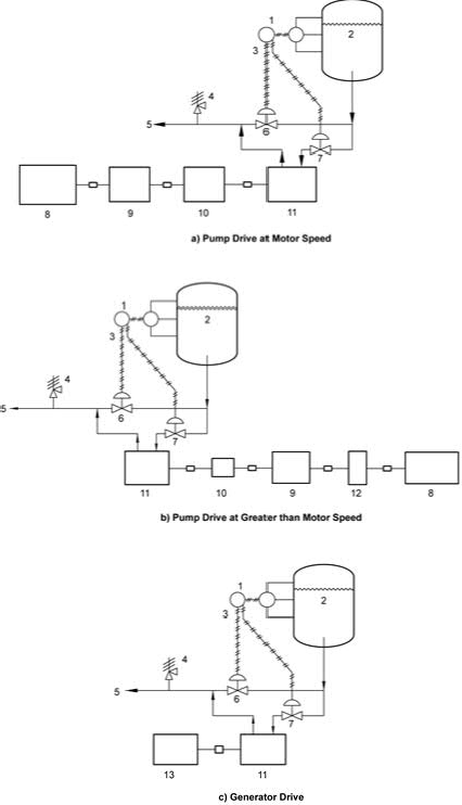
Key
1 level indicator, controller液位指示,控制器
2 high-pressure source高压源
3 split range分程控制
4 relief valve安全阀
5 low-pressure destination低压区
6 bypass旁路阀
7 inlet throttle valve入口节流阀
8 pump泵
9 motor电机
10 overrunning clutch超越离合器
11 HPRT液力透平
12 gear齿轮箱
13 generator发电机
==Figure C.1——Typical HPRT Arrangements==
==图C.1—HPRT的典型配置==
C.4 Testing测试
C.4.1 The HPRT shall receive a performance test at the manufacturer's test facility. Hydraulic and mechanical performance guarantees shall be based on water testing.
HPRT 必须在制造商的测试设施中接受性能测试。水力和机械性能保证应基于水进行的测试。
C.4.2 Figure C.2 shows recommended test performance tolerances for HPRTs. The pump criteria given in the main body of this standard are not applicable.
图 C.2 显示了 HPRT 的建议的性能测试允差。本标准正文中给出的泵标准不适用。
C.4.3 Vibration levels for HPRTs shall meet the criteria for pumps given in the main body of this standard.
HPRT 的振动级别应符合本标准正文中关于泵的标准。
C.4.4 If specified, the overspeed trip setting for the HPRT shall be verified at the manufacturer's test facility. If required, overspeed trip devices shall be checked and adjusted until values within 1 % of the nominal trip setting are attained. Mechanical overspeed devices shall attain three consecutive non-trending trip values that meet this criterion.
如有规定,必须在制造商的试验设施中验证 HPRT 的超速跳闸设置。 如有需要,必须检查和调整超速脱扣装置,直至达到额定脱扣设定值的 1%以内。机械式超速脱扣装置必须达到连续三个无趋势的脱扣值,以满足此标准。
::: tip
解释:three consecutive non-trending trip value,机械式超速保护装置应达到三次连续的保护动作,且每次的保护动作值都与设定值相同或接近,不出现上下波动的趋势。
实际中,因为超速跳闸装置的逻辑是,转速超过停车数值,就应该关闭液力透平的入口阀门,这里的超速脱扣,是电子超速保护装置,不是机械式的。
:::
NOTE Determining the runaway speed during a water test can be considered, but this speed can be accurately calculated once performance with water is known. Runaway speed for gas-rich steams cannot be determined by water tests.
注:可以考虑在水试验中确定失控速度,但一旦知道水的性能,就可以准确地计算出失控速度。富含气体的蒸汽的失控速度无法通过水试验来确定。
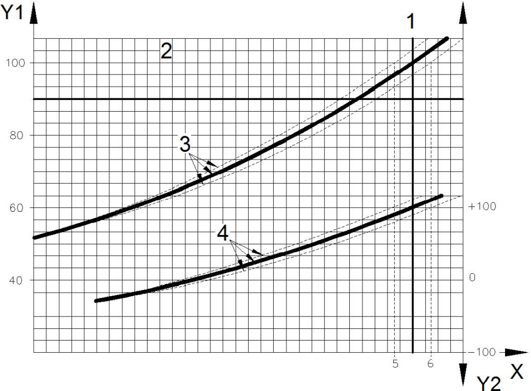
Key
X flowrate流量
Y1 differential head, expressed as a percentage 扬程差,用百分数表示
Y2 rated power, expressed as a percentage额定功率,用百分率表示
1 rated flow额定流量
2 rated head额定扬程
3 typical head vs flowrate curve典型的扬程VS流量曲线
4 typical power vs flowrate curve典型的功率VS流量曲线
5 low-side tolerance (95 %)下限允差(95%)
6 high-side tolerance (105 %)上限允差(105%)
==Figure C.2 HPRT Test Performance Tolerances==
==图C.2—HPRT测试性能允差==
::: tip
解释:从图中可以看出,其功率曲线和扬程曲线在预期的95%到105%都是可以接受的
但是振动指标应该符合泵的标准。
:::